Prepare to delve into the captivating realm of the NFPA 70E arc flash boundary, where electrical safety takes center stage. In this comprehensive guide, we’ll illuminate the significance of this boundary, exploring its definition, methods for determining it, and the crucial factors that shape it.
Stay tuned as we unravel the intricacies of arc flash boundary calculations, mapping, and safety considerations.
Understanding the NFPA 70E arc flash boundary is paramount for safeguarding workers and ensuring a secure electrical environment. Let’s embark on this journey of discovery together.
NFPA 70E Arc Flash Boundary Definition
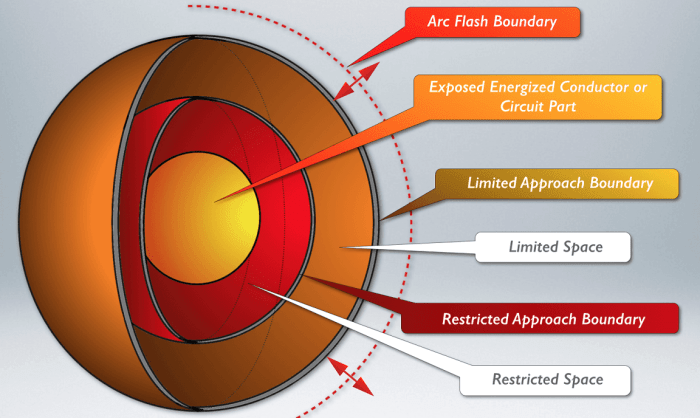
An arc flash boundary is a designated area surrounding electrical equipment where there is a potential risk of an arc flash.
Establishing an arc flash boundary is crucial for ensuring the safety of personnel working near electrical equipment. It helps in identifying the areas where appropriate personal protective equipment (PPE) and work practices are required to mitigate the risk of arc flash incidents.
Purpose and Importance, Nfpa 70e arc flash boundary
- Protects personnel from the hazardous effects of an arc flash, including burns, eye damage, and hearing loss.
- Ensures compliance with NFPA 70E, the industry-recognized standard for electrical safety.
- Provides a clear demarcation of the safe working area around electrical equipment.
- Facilitates the development of safe work practices and emergency response plans.
Methods for Determining Arc Flash Boundary
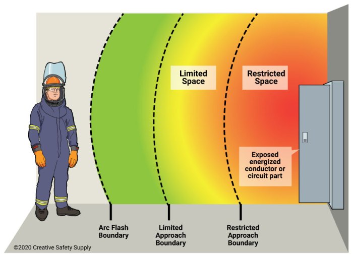
There are several methods available for determining the arc flash boundary, each with its advantages and disadvantages. The most common methods include IEEE 1584, NFPA 70E Table 130.7(C)(15)(A), and software modeling.
IEEE 1584 is a comprehensive standard that provides detailed guidance on arc flash hazard analysis. It includes a number of methods for calculating the arc flash boundary, including the simplified method, the detailed method, and the zone method. The simplified method is the most commonly used, as it is relatively easy to apply and provides conservative results.
The detailed method is more complex and time-consuming, but it provides more accurate results. The zone method is a hybrid approach that combines elements of the simplified and detailed methods.
NFPA 70E Table 130.7(C)(15)(A) provides a simplified method for calculating the arc flash boundary. This method is based on the available fault current and the distance from the arc source. It is a relatively simple method to apply, but it can be less accurate than the IEEE 1584 methods.
Software modeling is a computer-based method for calculating the arc flash boundary. This method uses a computer model to simulate the arc flash event and calculate the resulting arc flash hazard. Software modeling is the most accurate method for calculating the arc flash boundary, but it can also be the most time-consuming and expensive.
Advantages and Disadvantages of Each Method
| Method | Advantages | Disadvantages |
|---|---|---|
| IEEE 1584 | – Comprehensive standard- Detailed guidance- Accurate results | – Complex and time-consuming- Can be difficult to apply |
| NFPA 70E Table 130.7(C)(15)(A) | – Simple to apply- Conservative results | – Less accurate than IEEE 1584 methods |
| Software modeling | – Most accurate method- Can be used to model complex scenarios | – Time-consuming and expensive- Requires specialized software |
Factors Influencing Arc Flash Boundary
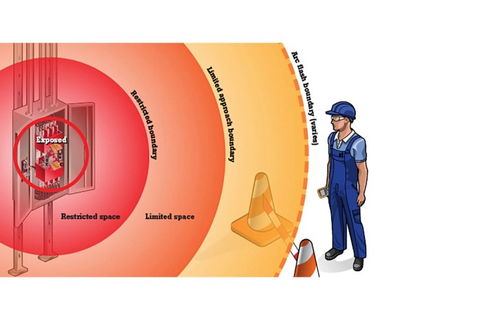
The arc flash boundary is not a fixed distance but rather a dynamic zone that can vary depending on several factors. These factors interact to determine the distance at which an individual is at risk of injury from an arc flash.
The arc flash boundary defined in NFPA 70E is crucial for electrical safety, as it helps prevent severe burns. Speaking of burns, have you come across the crossword clue “bone in ear”? If you’re stumped, check out this resource here . Returning to NFPA 70E, it’s essential to understand the arc flash boundary to ensure workplace safety.
System Voltage
The voltage of the electrical system is a primary factor in determining the arc flash boundary. Higher voltages result in greater arc flash hazards due to the increased energy available to sustain the arc. The higher the voltage, the farther the arc flash boundary will extend.
Available Fault Current
The available fault current is another critical factor influencing the arc flash boundary. Fault current refers to the amount of current that can flow through a fault in the electrical system. Higher fault currents lead to more intense arcs and, consequently, a larger arc flash boundary.
Equipment Configuration
The configuration of the electrical equipment can also affect the arc flash boundary. Factors such as the type of enclosure, the presence of arc chutes, and the spacing between conductors can influence the severity of the arc flash and the distance at which it can extend.
Working Distance
The working distance refers to the distance between the individual and the potential arc flash source. The closer the individual is to the source, the greater the risk of injury. As the working distance increases, the arc flash boundary decreases.
Arc Flash Boundary Calculations
Calculating the arc flash boundary using the IEEE 1584 method involves several steps. The formula for calculating the arc flash boundary is:
AFB = (V x 1.73 x S) / (4 x π x ε)
Where:
- AFB is the arc flash boundary in feet
- V is the nominal system voltage in volts
- S is the short-circuit current in amps
- π is the mathematical constant pi (3.14159)
- ε is the incident energy in cal/cm2
The following steps provide a guide to calculating the arc flash boundary using the IEEE 1584 method:
1. Determine the nominal system voltage
The nominal system voltage is the voltage of the electrical system at which the equipment is operating. This information can be found on the equipment nameplate or in the electrical drawings for the system.
2. Determine the short-circuit current
The short-circuit current is the maximum current that can flow through a fault in the electrical system. This information can be obtained from a short-circuit study or from the electrical drawings for the system.
3. Determine the incident energy
The incident energy is the amount of energy that is released by an arc flash. This information can be obtained from a table of incident energy values or from a software program that calculates incident energy.
4. Calculate the arc flash boundary
Once the nominal system voltage, short-circuit current, and incident energy have been determined, the arc flash boundary can be calculated using the formula provided above.
For example, if the nominal system voltage is 480 volts, the short-circuit current is 10,000 amps, and the incident energy is 1.2 cal/cm2, the arc flash boundary would be calculated as follows:
AFB = (480 x 1.73 x 10,000) / (4 x π x 1.2) = 10.3 feet
Arc Flash Boundary Mapping: Nfpa 70e Arc Flash Boundary
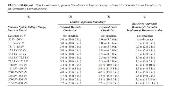
Arc flash boundary mapping is a critical component of workplace safety. It helps identify areas where workers may be exposed to hazardous levels of arc flash energy, allowing employers to implement appropriate safety measures.
Creating an Arc Flash Boundary Map
Arc flash boundary maps can be created using a variety of methods, including:
- Manual Calculations:Using formulas and data from NFPA 70E, engineers can manually calculate the arc flash boundary for specific equipment.
- Software:Specialized software programs can automate the arc flash boundary calculation process, making it faster and more accurate.
Benefits of Using Software for Arc Flash Boundary Mapping
- Accuracy:Software programs use precise algorithms to calculate arc flash boundaries, minimizing the risk of errors.
- Efficiency:Software can quickly generate arc flash boundary maps for multiple pieces of equipment, saving time and resources.
- Consistency:Software ensures that arc flash boundary maps are consistent with NFPA 70E requirements, reducing the risk of non-compliance.
Safety Considerations
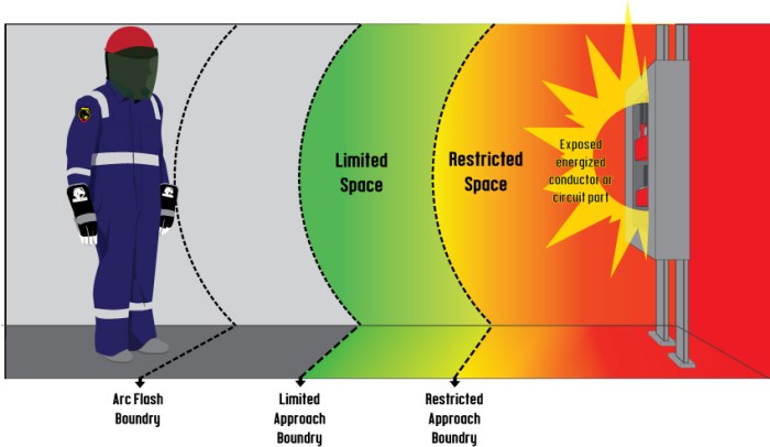
When working within the arc flash boundary, it is imperative to prioritize safety. This involves adhering to proper personal protective equipment (PPE) protocols, receiving comprehensive training, and implementing safe work practices.
Consequences of Exceeding Arc Flash Boundary
Exceeding the arc flash boundary can have severe consequences. An arc flash incident can result in:
- Severe burns
- Hearing loss
- Eye damage
- Electrical shock
- Death
FAQ Compilation
What is the purpose of an arc flash boundary?
An arc flash boundary is a designated safe distance from potential arc flash hazards. It helps protect workers from the intense heat, pressure, and shrapnel that can be released during an arc flash event.
How do I determine the arc flash boundary?
There are several methods for determining the arc flash boundary, including IEEE 1584, NFPA 70E Table 130.7(C)(15)(A), and software modeling. Each method has its advantages and disadvantages.
What factors influence the arc flash boundary?
Factors that can affect the arc flash boundary include system voltage, available fault current, equipment configuration, and working distance.
What are the safety considerations when working within the arc flash boundary?
When working within the arc flash boundary, it’s crucial to wear proper personal protective equipment (PPE), receive adequate training, and follow safe work practices. Exceeding the arc flash boundary can have severe consequences.